Per NFPA, IRI & FM Standards

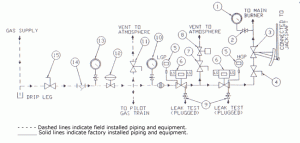
- Gas Burner Pressure Gauge – Wika 4″ dial, stainless steel case
- Gauge Shutoff Valve – 1/4″ N.P.T. needle valve
- Gas Flow Control Valve – Maxon, characterizable (12 points)
- Plug Valve with Wrench – Homestead
- High & Low Gas Pressure Switches – Ashcroft, with set point indicating pilot light
- Gas Safety Shutoff Valves – Maxon, normally closed, with proof of closure switches
- Three-Piece Full Port Ball Valve, lockable in the open position – Apollo
- Vent Valve – ASCO, normally open, full port
- Leak Test Valves – 1/4″ N.P.T. needle valves, plugged with 1/4″ pipe plug
Optional Equipment
10. Pressure Gauge with Shutoff Valve – Wika 4″ dial, stainless steel case with 1/4″ N.P.T. needle valve
11. Gas Train Supply Manual Vent Valve – Apollo full port with lockable handle
12. Main Gas Pressure Regulating Valve – Fisher
13. Pressure Gauge with Shutoff Valve – Wika 4″ dial, stainless steel case with 1/4″ N.P.T. needle valve
14. Gas Strainer
15. Plug Valve with Wrench – Homestead
Options
MG1
Main Gas Pressure Regulating Valve and Accessories – Includes items 10, 11, 12, 13 (shipped loose for field installation) and installation drawings and manuals. If option MG1 is selected, note the gas supply pressure on the burner package specification sheet.
MG2
Gas Strainer, Item 14, shipped loose for field installation
MG3
Gas Plug Valve with wrench, Item 15, shipped loose for field installation
NEMA 4
Changes item 8 to weatherproof (NEMA 4)
Specifications for Main Gas Train Piping & Fittings
2 1/2″ Pipe and smaller sizes
Schedule 40 pipe with 3000 lb forged steel threaded fittings
Pipe larger than 2 1/2″
Schedule 40 pipe with standard weight butt weld fittings
Gas Supply Pressure
To inlet of main gas train:
10 psig regulated, for units with heat inputs less than 120 MMBTU/Hr.
15 psig regulated, for units with heat inputs greater than 120 MMBTU/Hr.
Low Pressure Units:
If the regulated gas supply pressure is lower than that listed above, enter (S) in position 13 of the burner model number and specification sheet. Note the available gas pressure on the burner package.
Notes
The gas flow control valve, Item 3, will be an electric or pneumatic positioning type if the combustion control selected is one of the following:
- Upgraded Parallel Positioning System with flow control valve with integral actuator and positioner with position feedback
- Full Metering System


